TDA2030A 2.1 Stereo Amp 2 Channel Subwoofer Audio Amplifier Circuit Board DIY eBay
The TDA2030 amplifier chipset provides an excellent solution for constructing a subwoofer amplifier circuit. Nov 9, 2023 - In this article, we will discuss the working principle and specifications of the Subwoofer Amplifier Circuit TDA2030, as well as the accompanying BD711 and BD712 transistors used in its implementation.
TDA2030 Subwoofer Amplifier Circuit
Explanation of Subwoofer Amplifier Circuit TDA2030 JRC4558. The TDA2030 is a monolithic integrated circuit in a Pentawatt package that offers high-quality audio reproduction with low distortion and noise. It operates on a wide range of power supplies and delivers a maximum output power of 14W. The TDA2030 has excellent thermal and short-circuit.
TDA2030 Subwoofer Amplifier Circuit Top Circuits
The TDA2030A is a monolithic integrated circuit in Pentaw attpackage, intended for use as an audio class AB audio amplifier. Thanks to its high power capability the TDA2030A is able to provide up to 35W true rms power into 4ohm load@THD=10%,VS=36V,f=1KHz and up to 32W into 8ohm load@THD=10%,VS=44V,f=1KHz.Moreover, the TDA2030A delivers.

TDA2030 Amplifier Circuit Unleash Crystal Clear Sound! Electro Gadget
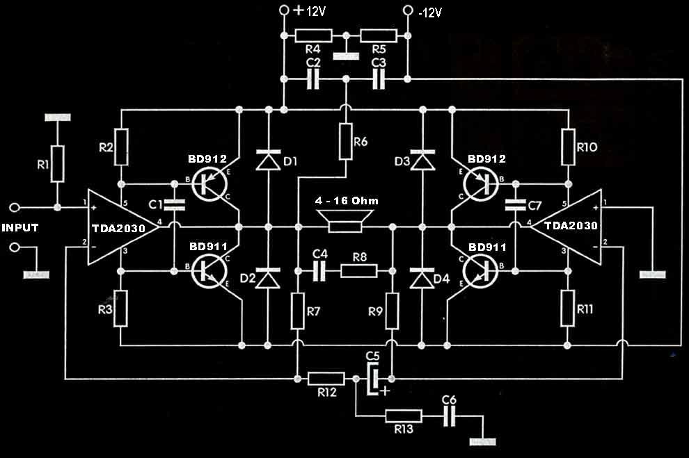
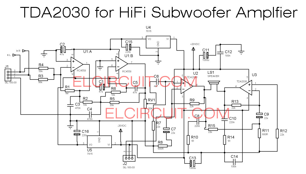
But that is a good idea, to use the tda2030 as amplifier of potency of system's surround, for the subwoofer the ideal is an assembly in bridge for more potency. Circuit diagram audio amplifier with tda2030a Schematic Of The Circuit Audio Amplifier With Tda2030 Suggestion of printed circuit board for assembly of the amplifier with tda 2030.
Tda2030a Subwoofer Amplifier Circuit Diagram
TDA2030 is a widely used 14W audio power amplifier monolithic integrated circuit in Pentawatt [ package, intended for use as a low-frequency class AB amplifier. However, some home theater prototype came with TDA2030 design has a problem of low volume. There are ways to increase the subwoofer performance that uses TDA2030A design.
TDA2030 2.1 Amplifier Board Subwoofer Circuit Diagram Xtronic
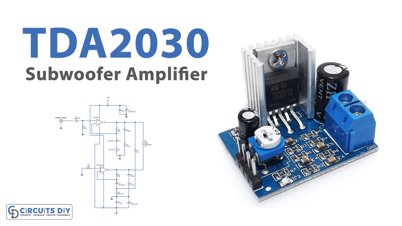
In this tutorial, we are going to make a "TDA2030 Subwoofer Amplifier circuit". A subwoofer (or sub) is a loudspeaker designed to reproduce low-pitched (bass and sub-bass) audio frequencies, these frequencies are lower than those which can be generated by a woofer. The typical frequency range for a subwoofer is about 20-200 Hz for.
Tda2030 Amplifier Circuit Diagram Pdf
The TDA2030 is a monolithic audio amplifier integrated circuit that can deliver up to 14 Watts of power. It operates on a single supply voltage ranging from 9 to 24 volts, making it suitable for a wide range of applications. The key advantage of this amplifier chipset is its simplicity and ability to drive subwoofers effectively.
TDA2030 Datasheet Audio Amplifier Circuits Pinout
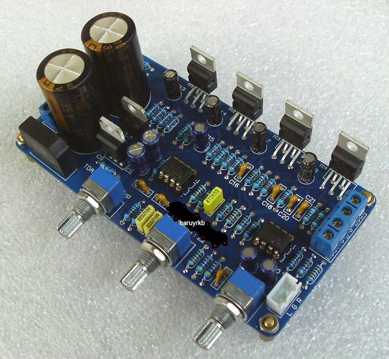
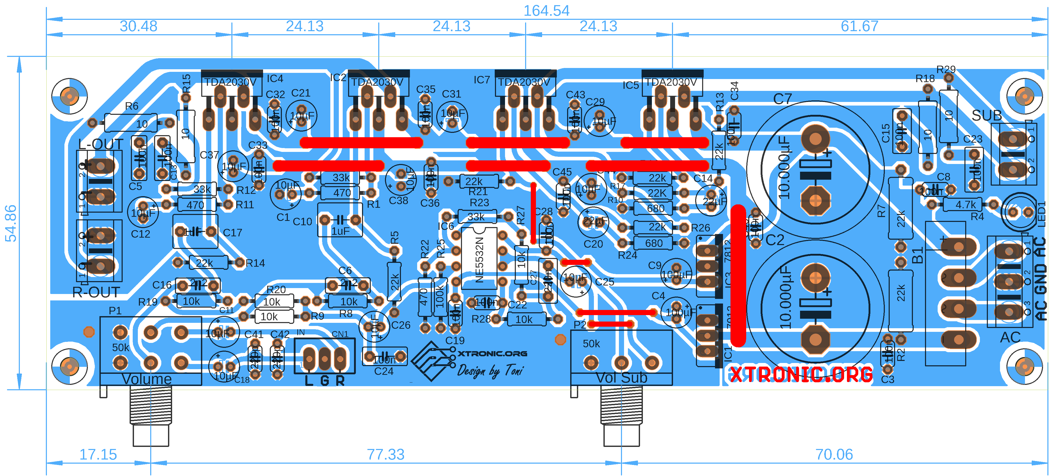
The circuit is divided into 3 parts: power supply, stereo amplifier and bass amplifier (subwoofer). TDA2030 2.1 amplifier board circuit diagram subwoofer. This circuit is a complete application is 2.1 amp, two satellite speakers for TDA2030 and one for the subwoofer, the 2.1 system, widely used in commercial applications as an amplifier for.
Tda2030 Audio Amplifier Circuit
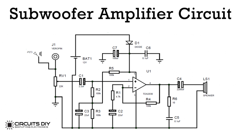
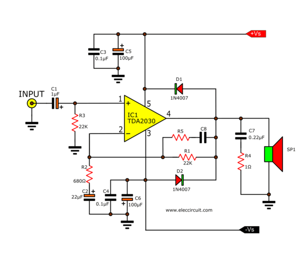
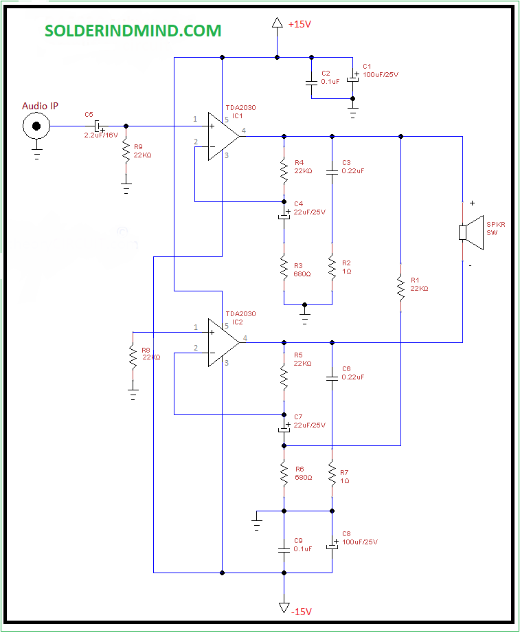
Above is the circuit Diagram for this TDA2030 based Amplifier Circuit. We have connected a 2.2uf capacitor in series to the non-inverting pin of the TDA2030, here it is acting as the High Pass Filter. So that it allows only the high frequency audio signal. There is a resistor (R4) between pin 2 and 4 we called that resistor as Feedback Resistor.
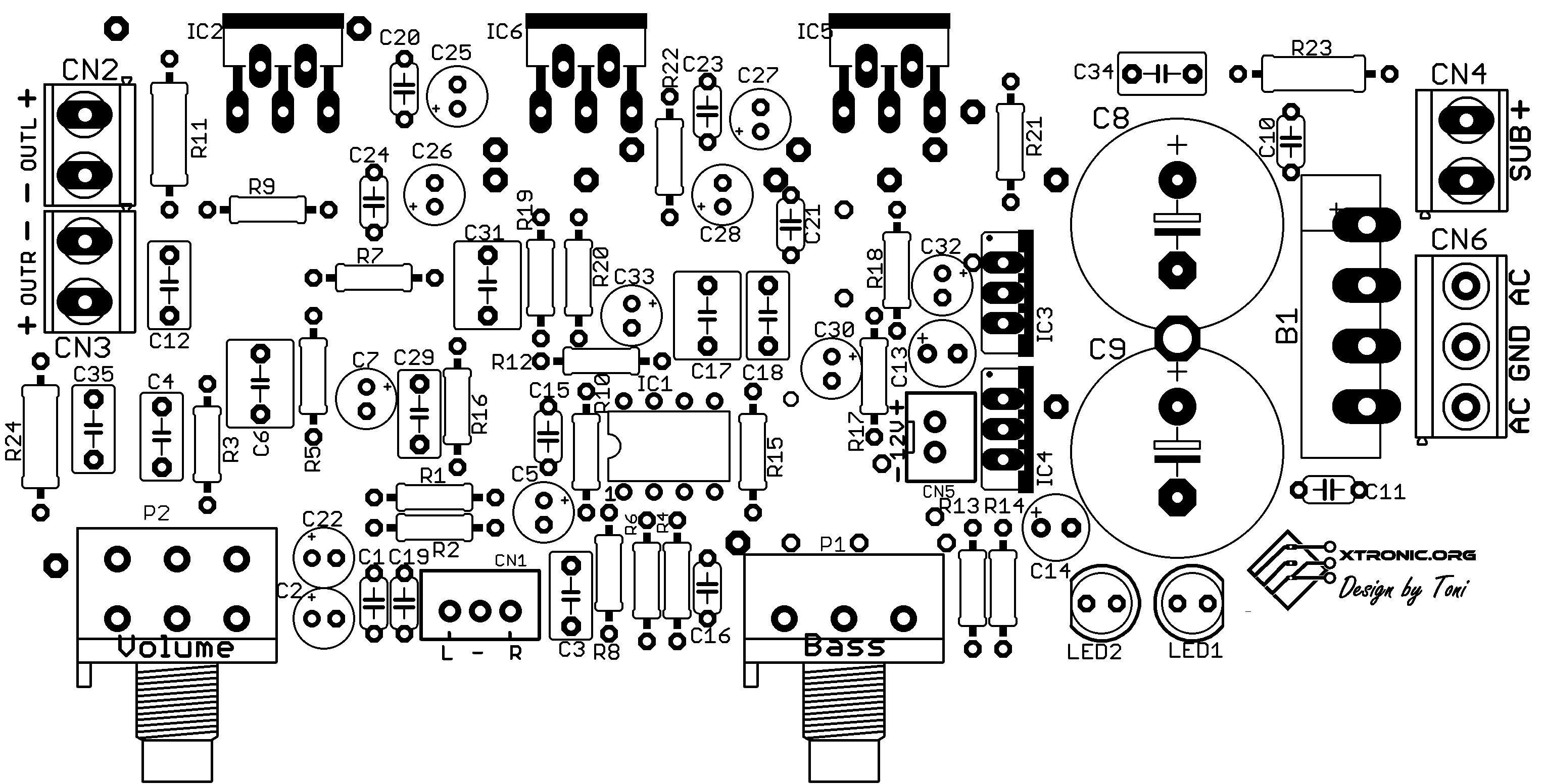
Circuit Power Audio Amplifier With TDA2030 2.1 3 X 18 Watts Xtronic
The TDA2030A is a monolithic IC in a Pentawatt package intended for use as a low-frequency class-AB amplifier. With V S max = 44 V it is particularly suited for more reliable applications without regulated supply and for 35 W driver circuits using low-cost complementary pairs. The TDA2030A provides high output current and has very low harmonic.
Tda2030 Amplifier Circuit Diagram Pdf
The required components used in TDA2030 IC subwoofer circuit are audio jack pin, IC TDA2030 IC, Resistors three-100K, one- 4.7 K and one-0 ohm, capacitors like one-100 mf, two-0.1 mf, two-2.2 mf & one-22mf, one- In4007 diode, one speaker, 12v battery, and one variable resistor with 22k value. The TDA2030 IC subwoofer circuit using 12v is shown.
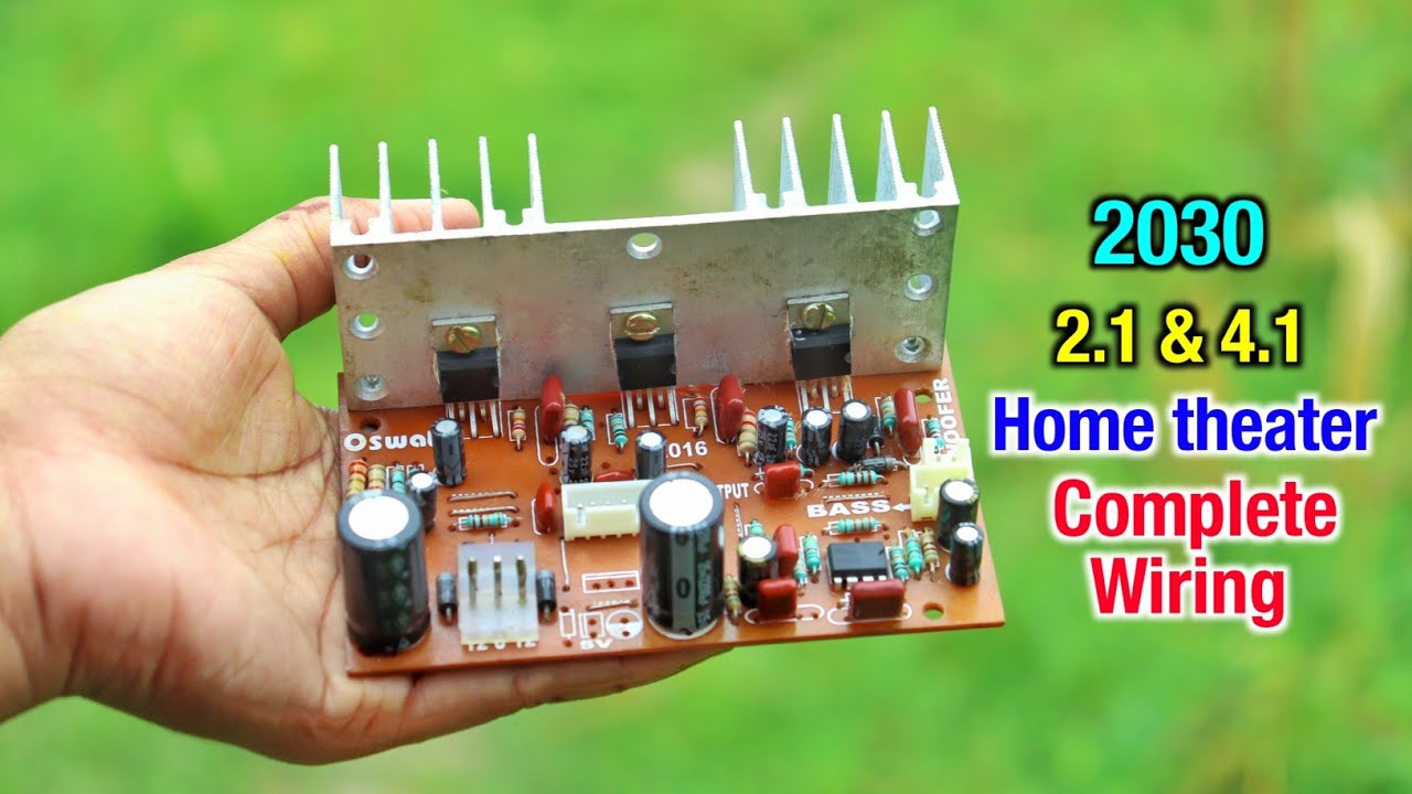
tda2030a 2.1 Subwoofer amplifier board wiring करना सीखें। हिंदी में। YouTube
The five TDA2030 leads are categorized as two groups to be connected with amplifier circuit. - Group 1: Pin 3 (-V power supply), Pin 5 (+V power supply) - Group 2: Pin 1 (Non-inverting audio input), Pin 4 (Audio out), Pin 2 (Inverting audio input) You will see later why TDA2030 leads are categorized as two parts.
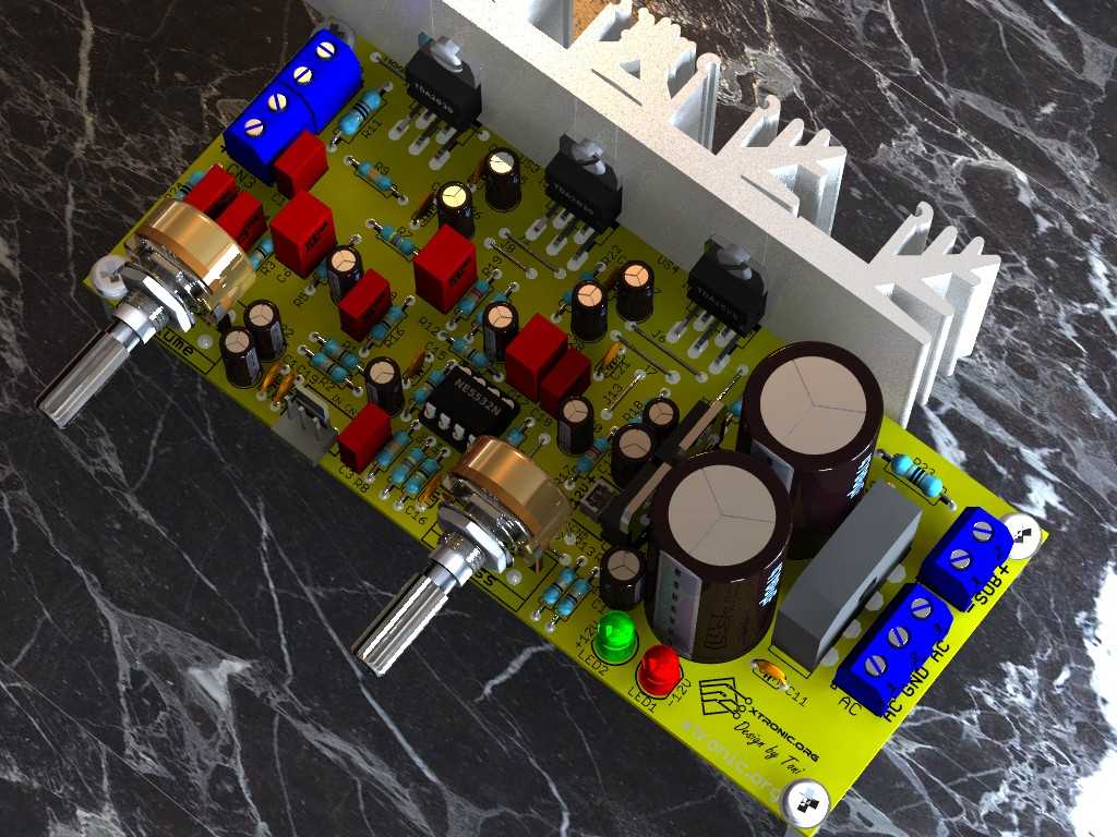
Circuit Power audio Amplifier with TDA2030 2.1 3 x 18 Watts Xtronic
The output of the TDA2030 is connected in series with the capacitor which allows the amplified signal to the speaker. This sub-woofer circuit has the ability to deliver 12 W output. Here, we can use around 4 to 6-ohm speakers. It is better to use a heat sink to remove the high temperature in the TDA 2030. If needed, you can also add a cooling.

TDA2030A 2.1 Stereo Amp 2 Channel Subwoofer Audio Amplifier Circuit Board Kit eBay
Step 2: Circuit Diagram and Working. · TDA2030 IC had 5 pins, 1st pin non-inverting, 2nd pin inverting, 3rd -ve negative power pin, 4th output pin, and 5th +ve positive power pin. · This is a single power supply circuit based Circuit, so the 3rd and 5th pin are connected to the power supply 12-volt dc. ·.

Tda2030a Circuit Diagram Manual Anne Circuit
So, now in this tutorial, we are going to the "TDA2030 Subwoofer Amplifier circuit". The TDA2030 is a monolithic integrated circuit. This IC provides 14W of output power and can be used as a low-frequency amplifier. This IC has a high output current, minimal harmonic distortion, and low crossover distortion.
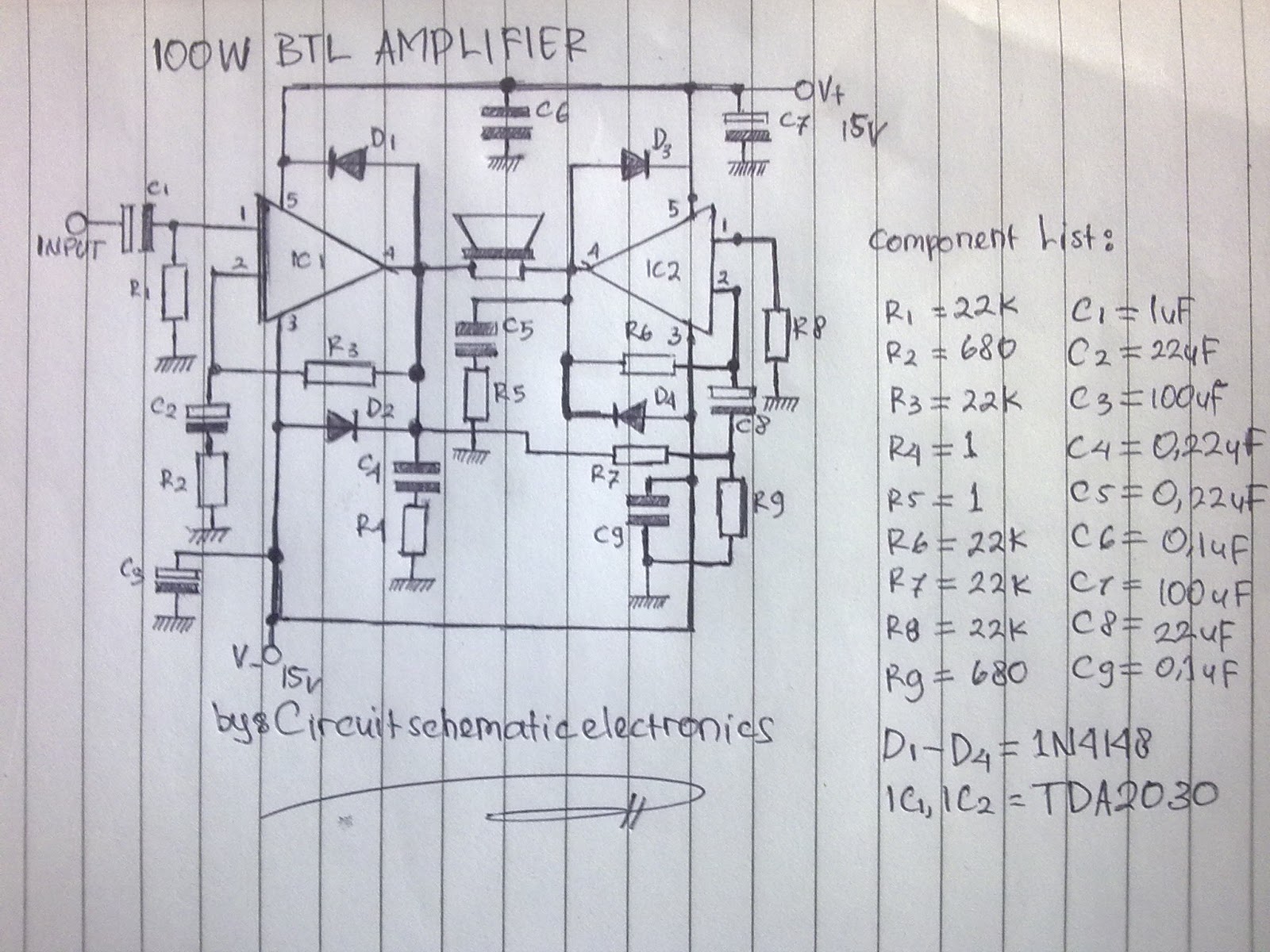
TDA2030 Bridged Subwoofer amplifier circuit Amplifier Circuits
This Subwoofer Amplifier using IC TDA2030 as a driver power amplifier and adding transistor booster using Transistor TIP3055 and TIP2955 1 Set. Output Power Amplifier about 200 Watt at voltage supply 30VDC.. However, use of these transistors can add distortion to the amplifier circuit. Use the power amplifier supply voltage is approximately.